
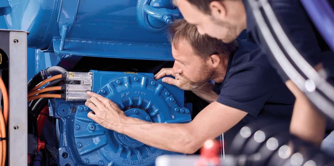
One of the most important aspects of the conversion is how to connect the gearbox to the new electric motor. This is usually done with an adapter plate that fits on both sides of the gearbox and the new motor.
This plate has to be designed and manufactured with very high precision, as the geometry of the transmission can be compromised if there are errors. There are manufacturers who sell ready-made and tested plates. The other option would be more time consuming, but may be cheaper, and that is to design it yourself. This has been my case, as so far no one has done the conversion, or made it public, on a Reanult Twingo.
So I decided to design it myself, and give the lathe operator a design of the plate itself.
The plate has to be made of a material that is hard, light and cheap. Aluminium is the perfect balance of these 3 variables, that's why the 99% adapter plates are made from aluminium.
The thickness of the plate depends on the torque and power of the electric motor. For a 14 Kw motor I was recommended a 17mm plate, but the turner only had 100mm and 20mm available (a paradox working with Alcoa), so I opted for the 20mm, this would not add much more weight and would improve the strength of the connection.
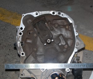
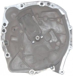
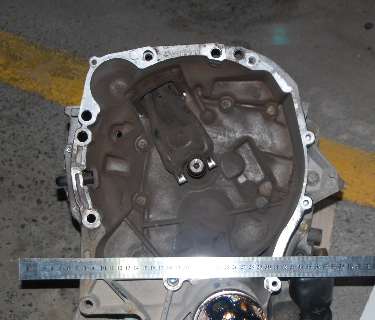
I started by disassembling the gearbox and making a template based on a front view photo.
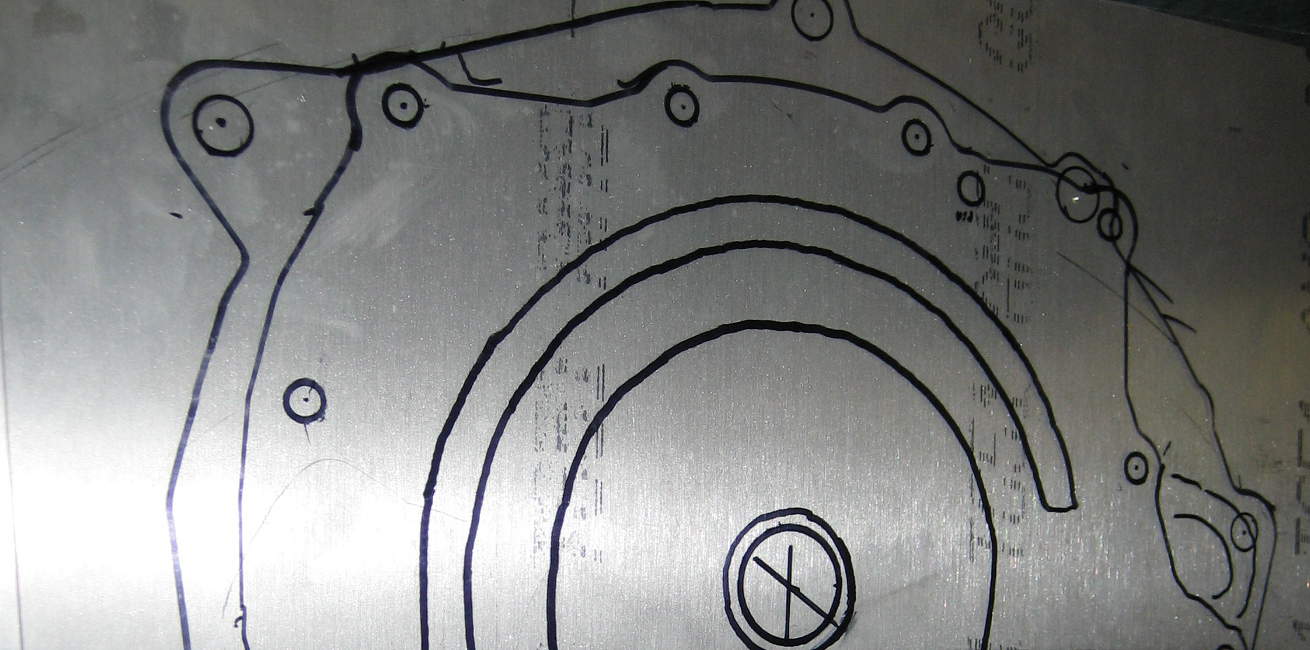
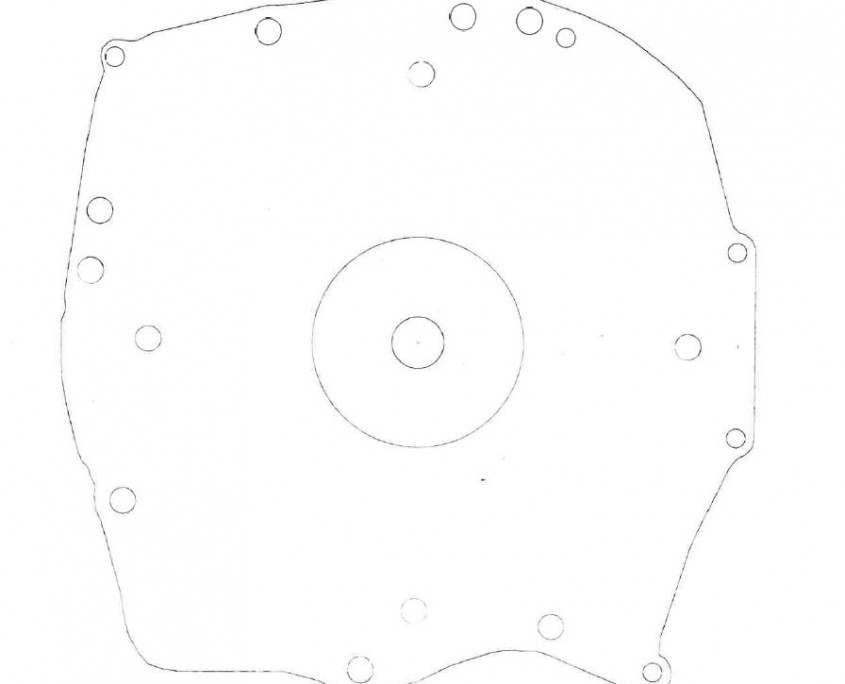
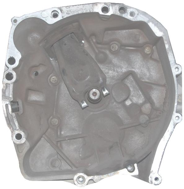
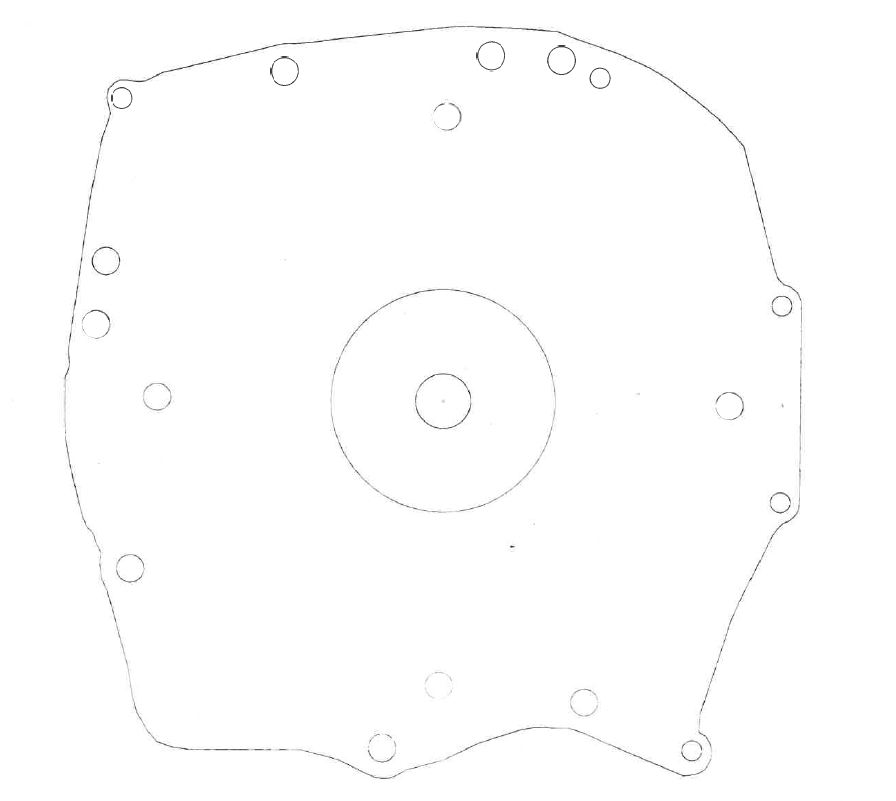
 After I had a suitable template, I edited it with a photo manipulation program (The Gimp) to get the silhouette.
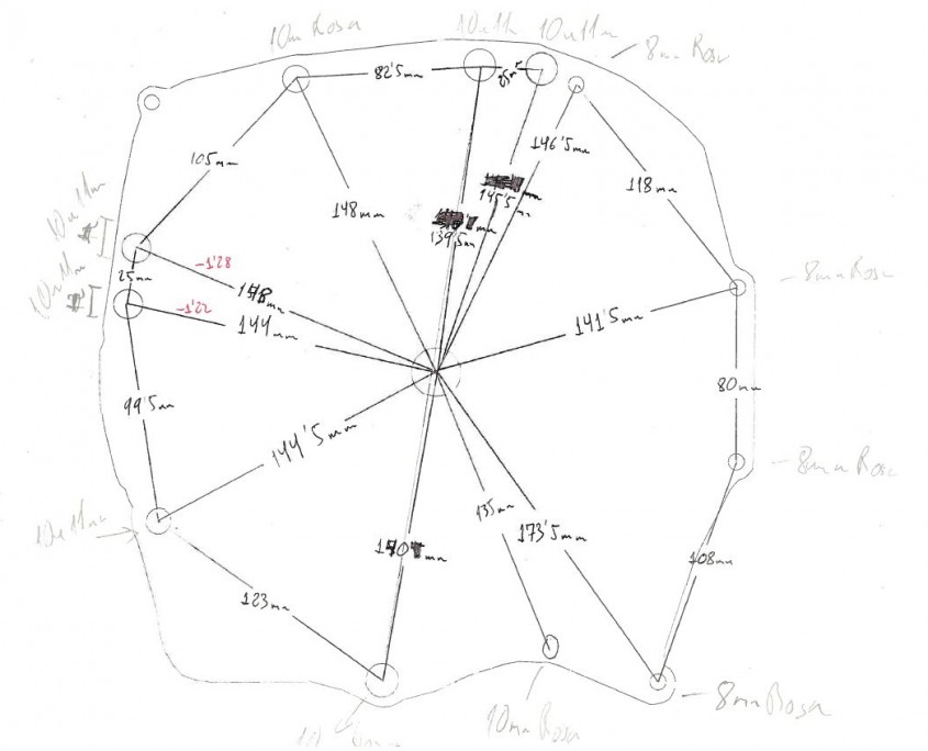
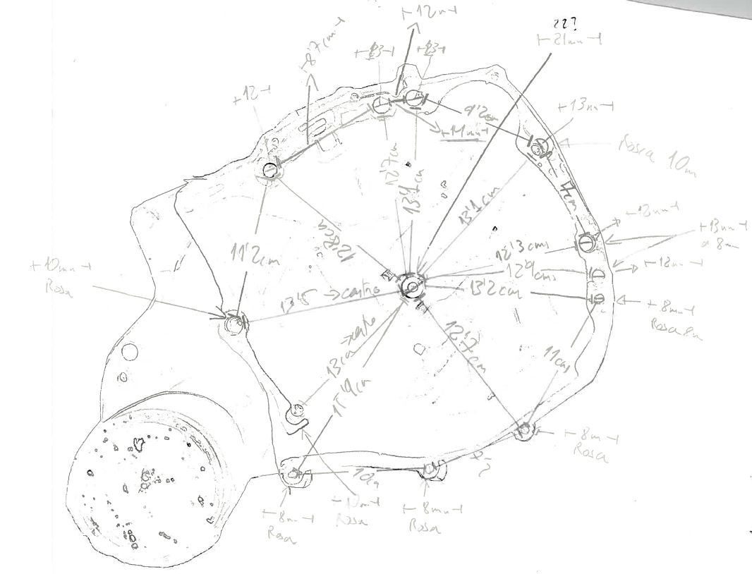
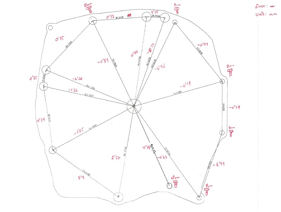
 Once the silhouette was obtained, I started to take measurements from the centre to the holes for the screws, between them as well, and so on, to get the real measurements.
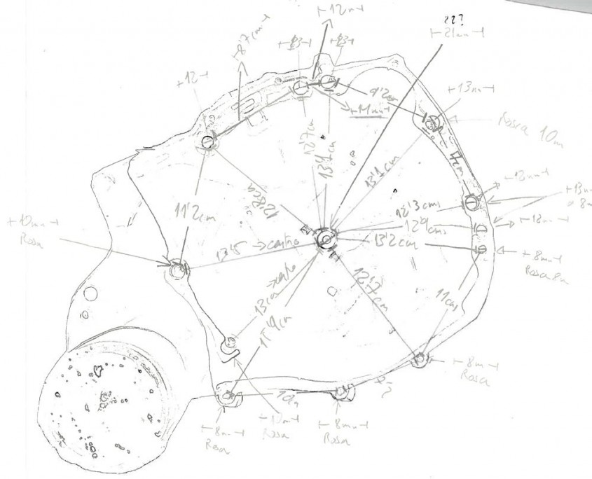 This is a procedure that needs to have zero margin of error, so I recommend using a good caliper for this. Once all the measurements are done (double and triple check them), draw the template in a 2D CAD program (LibreCAD), and draw plenty of reference lines at the centre and in between.
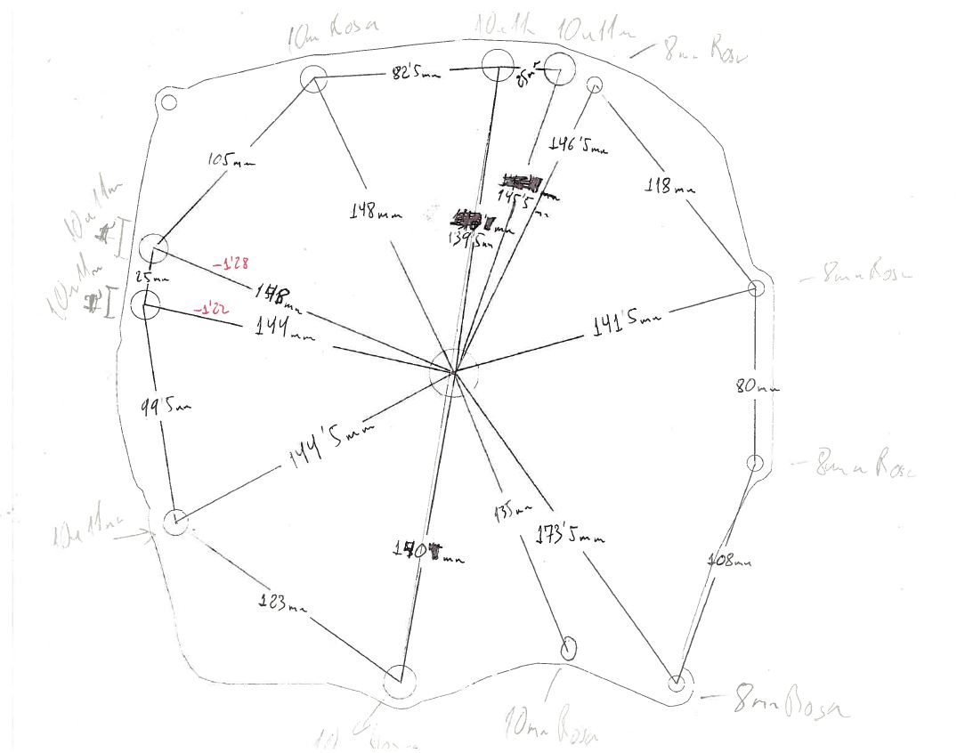
 Then, when I finished drawing all the circles for the screws, I measured inside the 2D CAD package all the lines and compared them with the real measurements. And... surprise, I got several errors.
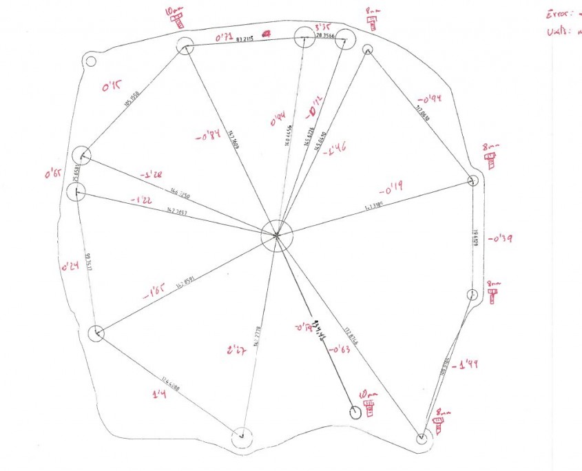 Next, I checked again the actual measurements and their positions on the 2D template, printed a full-size copy on paper to check that all the holes matched perfectly, so I gave the design the almost green light.
I took the final design to the lathe operator and asked him to make me a 1mm thick sheet metal template just to test the screws. They have a huge plotter type cutter that can cut 2cm aluminium like butter.
Next, I checked again the actual measurements and their positions on the 2D template, printed a full-size copy on paper to check that all the holes matched perfectly, so I gave the design the almost green light.
I took the final design to the lathe operator and asked him to make me a 1mm thick sheet metal template just to test the screws. They have a huge plotter type cutter that can cut 2cm aluminium like butter.
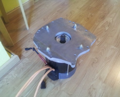
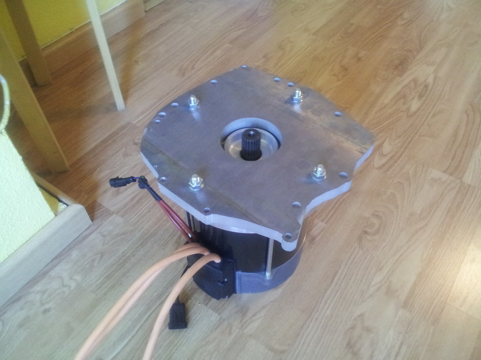
 So I tried the 1mm sheet metal template and it fit like a glove. Only one of the 8mm holes had an offset (about 0.5mm), the rest fit perfect. So I gave the green light 100% and asked the logger to make the same one in 20mm aluminium sheet. Although it took a while because they were out of material, they finally made it and it connects the gearbox with the electric motor perfectly.
 After I had a suitable template, I edited it with a photo manipulation program (The Gimp) to get the silhouette.
 Once the silhouette was obtained, I started to take measurements from the centre to the holes for the screws, between them as well, and so on, to get the real measurements.
 This is a procedure that needs to have zero margin of error, so I recommend using a good caliper for this. Once all the measurements are done (double and triple check them), draw the template in a 2D CAD program (LibreCAD), and draw plenty of reference lines at the centre and in between.
 Then, when I finished drawing all the circles for the screws, I measured inside the 2D CAD package all the lines and compared them with the real measurements. And... surprise, I got several errors.
 Next, I checked again the actual measurements and their positions on the 2D template, printed a full-size copy on paper to check that all the holes matched perfectly, so I gave the design the almost green light.
I took the final design to the lathe operator and asked him to make me a 1mm thick sheet metal template just to test the screws. They have a huge plotter type cutter that can cut 2cm aluminium like butter.
Next, I checked again the actual measurements and their positions on the 2D template, printed a full-size copy on paper to check that all the holes matched perfectly, so I gave the design the almost green light.
I took the final design to the lathe operator and asked him to make me a 1mm thick sheet metal template just to test the screws. They have a huge plotter type cutter that can cut 2cm aluminium like butter.
 So I tried the 1mm sheet metal template and it fit like a glove. Only one of the 8mm holes had an offset (about 0.5mm), the rest fit perfect. So I gave the green light 100% and asked the logger to make the same one in 20mm aluminium sheet. Although it took a while because they were out of material, they finally made it and it connects the gearbox with the electric motor perfectly.

Great help and very detailed process
Thank you very much. Although for the next conversion I think the design process needs to be improved.
Greetings
Thank you very much for reporting the process, I thought the electric motor was connected directly to the transmission.